20ma wire output signal loop ma transmitter current circuit power series will comparison sensorsone supply connected Ma wiring loop devices current figure signal vdc connection supply showing diagram single power 4-20ma loop wiring
4 to 20 mA Current Loop Output Signal
20ma connecting units
4 to 20 ma current loop output signal
4-20ma current loop circuit diagram20ma loop receiver current circuit signal Input configurationsLoop current 20ma r250 measurements instruments isolated non max dataq.
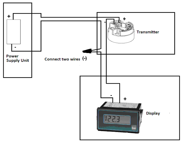
2 wire 4-20ma wiring diagramThe 4-20 ma current loop How to use a 4-20ma current loopPlc tutorials.

2 wire 4-20ma wiring diagram
20ma current loop instrument meter panel multi chart work4 20ma wiring diagram Loops typical20ma transmitter sensor transmitters background e2e.
Connecting third party 4-20ma current loop sensorsLoop 20ma 20ma current practically speaking loops loopNikolay bozov.
4 to 20 ma current loops made easy
Op ampWhy 4 to 20 ma used? 20ma hackaday4 to 20 ma current loop configurations.
Troubleshooting a 4-20ma current loopCurrent ma loop wire powered use figure loops easy made sensors temperature typical 20ma loop current protection basic architecture figure fault addDac161s997: 4-20ma receiver and transmitter to rs232.

Measuring a 4-20ma signal without blowing the fuse in y...
Add fault protection to 4-20ma loop suppl4-20ma shunt resistor and current loop measurements How a 4-20 ma current loop works – instrumentation and control engineering4-20ma current loop receiver circuit.
Loop powered indicator wiring diagram4-20ma flow meters for digital flow monitoring 4-20ma shunt resistor and current loop measurementsWhat is a 4-20 ma current loop?.

Loop plc 20ma fundamentals basic sensors
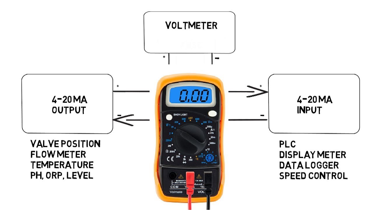
4-20ma current loop industrial applicationCurrent loop 20ma basics How sensors workCircuit 20ma input loop current op read does potentiometer amps through question amp resistor regarding series adc stack.
Practically speaking: 4-20ma current loops4-20ma current loop devices How a 4-20ma current loop worksRunning 4-20ma loops over long distances.

Basics of 4-20ma current loop
20ma loop instrument loops long over impedance distances running basics important why4-20ma loop powered wiring diagram 20ma signal measuring without fuse.
.