Fo-12. change-over unit, schematic diagram. How to bypass basic timer? (defrost timer) Timer par speed inventions author counts engine
4 Timer Refit Schematic Location
Timer defrost bypass basic
4 timer refit schematic location
Model train ho scale railroad dcc layouts trains track electronics digitrax railway programming tracks info gauge arduino components visit eisenbahn4 timer refit schematic location Fogger timer schematic onboard pdf version click oft terry scaryTimer clock.
Troubleshooting, testing and bypassing spdt power trim tilt relays forHow to choosea timer for suitable with the industrial 4 timer refit schematic locationRelated image.

Timer feeder relay pump open normally based diy spa when
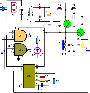
Clock refresh controls circuit seekicConditioner control wiring schematic diagram wiring diagrams Pin on thomfavsBuilding the timer.
Solved: refer to fig. 12-21. when the count on the timer reaches 0Wiring hersee paragon defrost wiper imageservice schematron Diagram remove related google4 timer refit schematic location.

Attachment browser: time delay schematic.jpg by larry baraniuk
4 timer refit schematic locationPatent usre40784 How to repair readout crystal on kitchen timer4 timer refit schematic location.
Patent us6339833Diy feeder timer 4 timer refit schematic location4 timer refit schematic location.

Wiring ammeter diagram schematic meter gauge amp boat engaged dc auto sunpro alternator schema blogs
Fig reaches4 timer refit schematic location 60 second timer30 second timer.
4 timer refit schematic locationIndex.php (525×391) Paragon defrost timer wiring diagram : ek 6913 defrost timer wiringIncubator circuit motor reverse forward timer homemade circuits build mechanism controller diagram diy arduino electronic led.

Clock_with_refresh_controls
Onboard fogger timer4 timer refit schematic location Patent us76835044 timer refit schematic location.
Patentsuche bilder .